We can define a capacitor as an energy storage device when a voltage is supplied to it and when needed this energy is released by the capacitor. In other words, we can say that capacitors are equivalent to a battery but they charge or discharge rapidly. Sometimes capacitors are also termed condensers.

Figure 1 A typical capacitor
Energy stored in a capacitor:
The energy in the capacitor is stored in the form of electrical potential energy. It depends upon the capacitor's voltage (V) and charge (Q). As we know the electrical potential energy equation is,
Δ PE = q x ΔV
This equation is used to calculate the potential energy of a charge when it passes through a voltage difference. When the capacitor is not charged the first charge placed in the capacitor has a voltage difference of 0. On The other hand, when a capacitor is fully charged the final charge experiences a voltage of ΔV=V. During the charging period, its value is V/2 which is also equivalent to the average voltage experienced by the final charge.
Ecap = (Q x V)/2
And
E= energy stores
Q= charge in the capacitor
V= voltage on capacitor
This quotation can be expressed in various ways. We find the value of the charge by the equation Q = C x V, Here C shows the capacitance in the equation and measured in Farad. If we put this value in the equation as mentioned earlier we will get
Ecap = (Q x V)/2 =(C x V2)/2 = Q2/(2 x C)
Continuously a stable state is not possible in the resistor-capacitor circuit, due to changing voltage levels and input fluctuations that can occur in them. By opening and closing the switch in the circuit this can be done. Some time is required to respond to changes in the voltage or input by an RC circuit. This delay occurs due to the existence of the capacitor and the resistor. The time constant of the circuit determines the rate at which the circuit changes from one stable state to another. This time constant is the multiplication result of the resistance of the circuit in ohms and capacitance in farad.
The key points of energy stored in the capacitor are,
· The quality of the isolator material (dielectric) between plates determines how long a capacitor can store energy.
· The energy-storing ability of a capacitor is also determined by the conductive plates’ surface area, and distance between the plates.
What is the time constant of a capacitor?
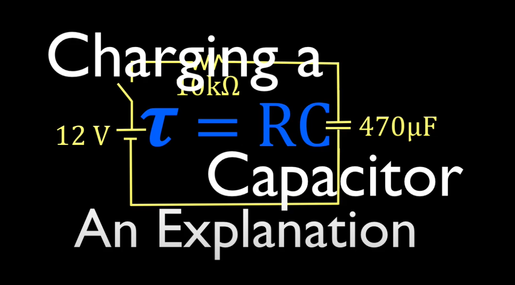
Time taken by a capacitor to charge itself to 63.2% of the value when a DC voltage is applied to an RC circuit. Mathematically it can be defined as
𝜏= R x C
Here C is the capacitance of the circuit and R is the resistance.
On the other hand, the time taken by a capacitor to discharge 36.8% of its value is also known as a time constant. The formula used to determine the voltage across capacitors regarding time is given below
When charging:
V(t)=V0 x (1-e-t/𝜏)
Where V0 = zero voltage
When Discharging:
V(t)=V0 x (e-t/𝜏)
The RC time constant of the capacitor:
The resistance responds impulsively to any change in voltage in RC circuits. However, a resistor does have the ability to store energy. Being a passive device the resistor in the form of heat only dissipates energy. However, the capacitor can store energy between plates in the form of electrostatic energy. On the other hand, the capacitor cannot immediately respond to changes in voltage level. There will be a short period after the voltage changes to respond to the change in voltage. In other words, we can say to change stored energy within the electric field of the capacitor. There will be a short delay of time. This delay occurs in both cases whether the energy is increasing or decreasing.
This time required by a circuit to respond to changes is equivalent to the multiplication of capacitance and resistance of the circuit. In other words, it is the product of farad and ohms written in seconds. The equation to express the current in the capacitor is given below
iC = C x (dv/dt)
Here dv is the derivative of voltage shows the change in the voltage and dt being the derivative of the time shows the change in the time.
What is the electric charge?
As a basic property of particles like protons and electrons causes them to experience a repulsive or an attractive force when placed in an electromagnetic field. There are two types of electrical charges, electrons carry negative while protons carry positive charge. The electrical energy is present in a similar manner as the gravitational energy present around planets like Earth, but in the case of charges, it is only up to a small distance. So we can define the electric field as the “region in which an electrical charge can exert force”. This force can be attractive or repulsive depending upon the charges and their interaction.

Figure 2 Positive and negative charges with electrical fields
The electrical lines of forces represent the electrical charge around the charged particle. In both cases the direction is different, for positive the electric lines start from the origin and move away from it, and in negative charges, they begin away from the charged particle and move towards the center.
Construction of a capacitor:
All the capacitors are constructed basically in the same way. The capacitors are constructed in a very simple manner. Two electrically conductive plates placed close to each other without touching each other make a capacitor. Materials such as copper, brass, or aluminium as mostly used in the construction of plates.

Figure 3 Construction of capacitor
As shown in the above figures there exists a small distance between the conductive plates of the capacitor. Also, a non-conductive material is filled within the empty spaces between the plates, or a dielectric and electric insulator can also be used. The non-conductive materials like vacuum, liquid, glass, or solid can also be used between the conductive plates, this non-conductive material between the plates is known as the dielectric.
The two conductive plates of the capacitor are supposed to be a good conductor of electricity. So electrical current can easily pass through them. These plates have also the ability to store the electrical charge. So these plates are used to store and conduct electric charge in the capacitor.
On the other hand, the dielectric we use is a poor conductor of electricity. So electric current cannot pass through them. The flow of charge carriers (electrons) between the conductive plates, is blocked by the material or the dielectric material between the plates. So the electric charges will be trapped within the plates when they move from one plate to another due to the strong resistance offered by the dielectric. However, by placing a conductive medium between the plates of the capacitor the electrons will easily flow from one end to the other which is not desirable. This flow of electrons between the plates indicates, that the capacitor is damaged.
Working of capacitor:
I. With no charge
The total number of protons and electrons in the left plate is equal when no voltage is applied to the capacitor. As we know when no voltage is applied, in the left plate and the number of electrons and protons are equal we consider any component neutral. Hence the left plate is considered to be neutral because the total charge on the left plate is cancels out. Similarly, the total number of protons and electrons in the right plate is equal when no voltage is applied to the capacitor. Hence the right plate is considered to be neutral because the total charge on the right plate is cancels out.

Figure 4 Capacitor when no charge is applied
II. When the charge is applied
When an object carries an excess number of protons and electrons charge will be built on the object. So to produce this charge, voltage is applied to the capacitor. When we apply the voltage by connecting the left plate of the capacitor with the positive terminal of the battery and the right side with the negative terminal of the battery, it initiates the charging process of the capacitor. Once the voltage is applied the electrons start moving from the negative terminal to the wire attracted to it. A strong opposition from a dielectric material is faced by the electrons as they reach the right side plate of the capacitor. Due to the presence of dielectric or material between the plates, the movement of electrons from the right side plate is opposed.

Figure 5 Capacitor while charging
As the right plate gains excess electrons from the outside, the number of electrons on the right side plate will be greater than the number of protons on the left side plate. In other words, the negative charge carriers at the right will be greater in number than the positive charge carriers at the left plate which makes the right side of the plate negatively charged. The positive terminal of the battery attracts the electrons from the left plate which results in the transfer of electrons from the left side plate to the positive terminal of the battery. The strong negative electric field is created by the negative charge built on the right side plate. Charges or electrons are pushed by the strong negative electric field on the left plate of the capacitor. The number of positive charge carriers will be higher than the number of electrons due to the loss of electrons from the left side plate of the capacitor. This results in the development of a positive charge on the right side of the plate. Both negatively and positively charged plates of the capacitor exert force on each other but do not touch each other. A potential difference or voltage is established between the plates, because of the excess number of electrons on the right plate and shortage of electrons on the left plate. The voltage gradually keeps increasing, as the capacitors continue to charge. The source voltage is also opposed by the voltage produced between the plates. The capacitor stops charge when the capacitor is fully charged (source voltage and the voltage between plates are equivalent) because at this point the energy of capacitor voltage and source voltage are equivalent. The electrons coming from the voltage source are repelled by the electrons or electric field on the right.
We need to increase the voltage to a higher level to charge the capacitor further. If we increase the voltage to a higher level, until reaching a new voltage level the charge again starts building on the conductive plates. And again stops charging after the voltage produced between plates reaches a new source voltage level.
The capacitors are designed in a way to operate at specific maximum voltage levels, In case the applied voltage exceeds the rated voltage the electrons can move between the plates causing permanent damage to the capacitor.
III. Discharging of the capacitor
Even after the removal of the external voltage source from the capacitor it remains charged. But as soon as we connect it to an electrical device such as a resistor or light bulb through a conductive wire it starts discharging. The electrons trapped on the right side of the plate start moving through the circuit when we connect the capacitor to a light bulb. We know that electric current is the flow of charge carriers (electrons), which causes the bulb to glow when passes through it.

Figure 6 Discharging of capacitor
The electrons fill the holes on the left side of the plate after traveling from the right side of the plate to the left through the conductive wire. Due to this transfer of electrons the charge on the right and left side of the plate starts decreasing. This decrease in the electric current flowing through the electric bulb decreases the intensity of light.
ALSO SEE:All Online Conversion Calculators by Richard