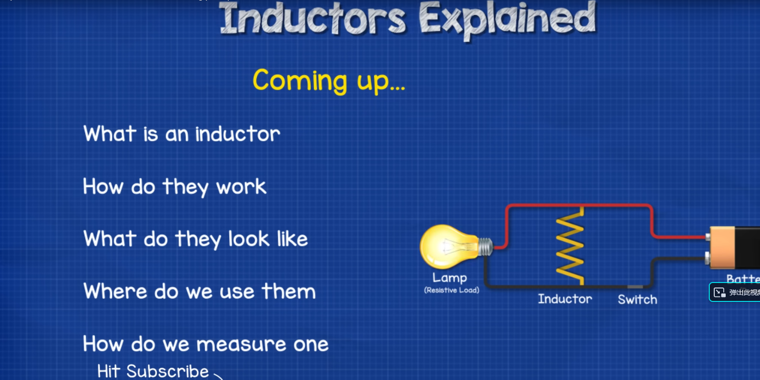
A turn is an individual loop of the wire. Insulation is used between these turns to prevent the short circuit. Commonly used insulations are plastic or enamel coating. Material like plastic is wrapped around the coil to secure the winding. To learn more about inductors and electromagnetic coils, their working principle how we use them here is a video.

Figure 1 A coil
Physical Properties of Coil
I. Stiffness of coil
This is one of the most essential characteristics of the coil, which depends upon various factors. The stiffness of the coil is proportional to the fourth power of diameter (D1) and increases with an increase in diameter. The cube of the mean diameter (D2) decreases the stiffness and is also associated with the G power of the wire being used, causes fewer wraps per unit length, denser the wire, and larger diameter increase the stiffness.
II. Diameter of coil
Diameter determines the stiffness as well as the capacity to endure external pressure like tension and compression.
III. Wire density of coil
The density of wire (G) employed in the construction of the coil greatly affects the coil’s rigidity. The greater the value of the density greater the stiffness
IV. Mean diameter of the coil
The stiffness is inversely proportional to the mean diameter of the coil. The stiffness level will be lowered for the coil featuring a smaller average diameter
V. Number of wraps of coil
During the creation of the secondary layout (also known as the primary winding of the coil), the quantity of the coil wound per unit length (n) is inversely related to the stiffness. The lower number of wraps will result in higher stiffness of the coil.
VI. Composition of coil
The physical characteristics of a coil greatly depend on the configuration of the coil, compromising its material used and quantity. For example, coils can be increased in strength or enhanced resistance to corrosion when crafted from specific alloys
VII. Detachment mechanism of coil
The detachment mechanism type or material employed can affect the coil's operational effectiveness and physical properties because of the way the coil is disconnected.
VIII. Size of coil
The dimensions of a coil play a vital role in determining its physical properties, for example, a larger coil will have distinct physical characteristics compared to a smaller one.
IX. Shape
The shape can affect the physical properties and efficiency depending upon the configuration as per the curvature and orientation of the wire used in the coil.
X. Material Properties
The properties of materials we use in the coil have a vital role in determining the properties of the coil. These properties include Passion’s ratio, Young’s modulus and density of the coil, performance, and other physical properties.
Types of coils:
We distinguish inductors in three ways, by their type of core, their shape or construction, and whether the inductor is adjustable or not.
A. Types based on cores:
The types of coils based on their core are discussed in detail below.
I. Air core
As the name suggests the air core coils require no medium to store magnetic energy, instead of using any other material it leverages air as a medium. These types of coils have several advantages due to the absence of a ferromagnetic core. These include no core saturation, high linearity, and no iron losses at high frequencies. These coils are easy to construct, which makes these coils more suitable for communication devices. A high induction value for these coils is not possible because these coils are larger in size and exhibit low factors. The diagram below illustrates an air core coil.

Figure 2 Air core coil
II. Ceramic core
No magnetic ceramic material is used in the construction of these coils. The shape of the coil and its terminal are provided by the non-magnetic ceramic material. As the ceramic core is a non-magnetic material the magnetic permeability is low resulting in the lower inductance. But the core losses are minimal in these types of coils and high inductor values are not possible. The diagram below illustrates a ceramic core coil.

Figure 3 Ceramic core coil
III. Ferrite core
By wrapping a wire around a ferrite core we can make this coil. A mixture of iron oxide Fe2O3 with a small percentage of different metal oxides like nickel, zinc, barium, and magnesium the ferrite material is obtained. The temperature for the process is kept between 1000 to 1300 OC. The diagram below illustrates a ferrite core coil.

Figure 4 Ferrite core coil
IV. Iron core
As the name suggests these coils are formed by the winding of a conductor around an iron material. Iron core coils contain relatively higher impedance values, because of the material used in iron coils. The diagram below illustrates an iron-core coil.

Figure 5 Iron-core coil
B. Types based on core design:
The types of coils classified based on their core design are discussed in detail below.
I. Bobbin-based coils
A wire in a special type of bobbin that is cylindrical in shape and is enclosed in a shrink tube can construct this coil. This coil has the same properties as a ferrite inductor because the core here is made up of ferrite. The diagram below illustrates a bobbin-based coil.

Figure 6 Bobbin-based coil
II. Toroid-core coils
This type of coil is constructed by winding a length of wire around a doughnut-shaped core. Ferrite is the material we use in these coils, so it also has the same properties as of ferrite coil. This type of coil generates stronger magnetic fields because of its closed-loop nature. Therefore these coils increase the size and have high inductance. With only a few windings due to high impedance by high magnetic field and high inductance, the toroid coils have improved efficiency. The diagram below illustrates a toroid-core coil.

Figure 7 Toroid core coil
C. Types based on core usage:
The types of coils based on their core usage are discussed in detail below.
I. Multilayer chip coil
As the name suggests, these coils consist of multilayers of thin plates of ferrite material. A special metallic paste is used to print coil patterns because the sheets are placed one layer after the other properly forming a coil. The diagram below illustrates a multilayer chip coil.

Figure 8 Multilayer chip coil
II. Thin film coils
Through a very thin ferrite or other magnetic material, these coils are constructed. By placing a spiral-shaped trace of copper that is conductive in nature and by a substrate we construct these coils. The thin film allows the stability and resistance to vibrations. The diagram below illustrates a thin film coil.

Figure 9 Thin film coil
III. Couples inductor coils
On a single core, by winding two wires we can construct these coils. The windings can be both, parallel or series connected depending upon the application. These coils work on the phenomenon of mutual induction. The diagram below illustrates a coupled inductor coil.

Figure 10 Coupled-inductor coil
IV. Power inductor coils
These coils are designed in a way that, without reaching the region of magnetic saturation they can withstand high currents. To increase the saturation current rating the inductor's magnetic field is increased. EMI (known as electromagnetic interference) increases in these coils due to an increase in the inductor’s magnetic field. To reduce the EMI, proper shielding is used in most of these coils. The diagram below illustrates a power inductor coil.

Figure 11 power inductor coil
V. Choke coils
It’s a very simple type of coil, but to block (choke) high-frequency signals these coils are designed. The impedance of the choke is increased significantly due to an increase in the frequency. So these coils block the high AC and allow low-frequency AC and DC signals to pass. The diagram below illustrates a choke coil.

Applications of the coil:
Coils in different electromagnetics systems have a wide range of applications. Below is a summary of a few major areas of applications like research, magnetic recordings, research, and the electrical industry where we use coil-based electromagnetic systems.
I. Modern telephone systems
The reed relay is an essential component of modern-day telephones. For complex routing of connections, it also includes solid-state circuits. A U-shaped yoke having coils wound on each leg is an electromagnetic structure of a receiver.
A coil causes the magnetic attraction of a soft iron diaphragm when an electrical current passes through the coil. By an amount proportional to the magnitude of the current the diaphragm is deflected and generates the sound waves after moving back and forth. Although modern technology and improvements in magnetic material have increased the sensitivity of the receiver, the basic structure of the diaphragm has remained unchanged.
II. Loudspeakers
The working principle for loudspeakers is as the receiver or earphone but here we require a larger volume of air to displace. The diaphragm consists of a flexible cone-shaped structure. The cone covers a larger area equipped with a coil of fine wire on a smaller ring existing at its apex. A powerful magnet of a cylindrical shape covers the ring.
III. As a tuning circuits
Inductor coils are used as tuning circuits because, with the help of it, we can select the desired frequency. The inductor along with capacitor types are used in several electronic devices such as television (to modify the frequency for selecting the desired channel) and for radio tuning circuits.
IV. As sensors
As contactless sensors inductive proximity sensors are very reliable. The opposition by the magnetic field in the coil to the flow of electric current is caused by inductance. To detect the traffic density the proximity sensor is used for this purpose.
V. To store energy in a device
The energy is stored in a current-carrying coil as a magnetic field for a small period and it will gone once the power supply is removed. This property makes the current-carrying coil useful in computer circuits where the power supplied can be switched.
VII. In induction motors
The shaft in induction motors will rotate due to the presence of a magnetic field produced by AC in the coils. We can control the speed of the motor according to the frequency of the power supply.
VIII. As transformers
A transformer is a combination of multiple inductive coils with a shared magnetic field. In power transition systems transformers play a vital role. As step-up and step-down transformers, they increase or decrease the power transmission.
IX. As filters
Inductive coils when they are combined with a capacitor can be used as filters. We can limit the input signal’s frequency when it enters the circuit by the addition of these filters in an electronics circuit.
X. In chokes
When AC flows through the inductors, it will create a current that will flow in the opposite direction of the AC. This causes the choking of AC and lets the DC pass. Where the AC supply is converted into DC this mechanism is very useful.
XI. As ferrite beads
Ferrite beads are a useful component of many computer parts and charging cables of cell phones. The frequency of the radio interface created by charging cables is reduced by the ferrite beads.
XII. As relays
Relays are one of the most popular switching devices, a magnetic field is created with the use of the inductor coils in the switches, whenever the flow of AC comes in contact with the switch.
ALSO SEE:All Online Conversion Calculators by Richard