
So a type of attenuator having an additional resistive component across its two series resistors acting as a bridge between them is known as the bridge tee attenuator circuit. As the signal appears to the bridge across the tee pad network the level of signal is reduced by the required attenuation without changing the characteristic impedance of the circuit by the additional resistive element. The input source and output load impedances are always equal to the series resistances of the original tee-bridged attenuator. The diagram below illustrates the circuit diagram of the bridge tee attenuator.

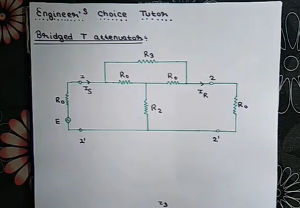
Figure 1 A simple bridged tee attenuator
As shown in the above diagram the resistor R3 acts as a network between two resistors R1 and R2 of a standard tee pad attenuator. The bridged tee attenuator tends to match itself to the transmission lines characteristic impedance which is one of the major advantages of using the bridged tee attenuator. However due to equal values of input or source impedance ZS and the output or load impedance ZL. It cannot be used for impedance matching which is a disadvantage of bridge tee attenuator. Designing of the bridge tee attenuator is as simple as designing a standard tee attenuator. As we know the values of two series resistors are equal so these resistors require no calculation.
R1 = ZS = ZL
R2 = R1 / (K-1)
R3 = R1 ( K-1 )
Here Z represents the source or load impedance and K represents the impedance factor.
Applications of bridged tee attenuator:
Attenuators are mostly used in the RF application as well as bridged tee attenuators which consist of a network of resistors. For making a signal or in other words, attenuate a signal coming from a source to a level that is stable for the receiving end. So the tee attenuator also plays a vital role in the prevention of any damage to the receiving side of the RF system. It also fulfills the requirement for maximum power transfer by matching the impedance between the source and the destination of a signal.
A modified version of the pi network topology is the bridge tee attenuator. And of major advantage for using the bridge tee attenuator over the other types of attenuator is we can use it where we require the varying attenuations with two resistors as per our requirement.
We can also use the bridge tee attenuator for matching impedance at high attenuation levels. So we can use the full range for resistor values of R1 and R2 in the case of the bridged tee attenuator as compared to the other types that have limited values of ranges.
Types of bridged tee attenuator:
Bridged tee attenuator has different other types per application we will discuss them in detail below.
I. Variable bridged tee attenuator:
As we know, the bridged tee attenuator can be designed by fixing a 3rd resistor R3 acting as a network between the series resistors R1 and R2. Now we have a clear idea about the construction of a bridge tee attenuator that consists of 4 resistive elements, where two of which we use to calculate a given amount of attenuation, and two are used to match the characteristic impedance of the signal.
By using a potentiometer or resistive switch instead of attenuator resistive elements we can get a variable bridged tee attenuator equipped with a predetermined range of attenuation as shown in the diagram below.

Figure 2 Circuit diagram for variable bridged tee attenuator
II. Adjustable bridged tee attenuator:
By doing careful calibration of the dual gang potentiometer we can get a fully variable bridged tee attenuator as illustrated by the diagram below.

Figure 3 Adjustable bridged tee attenuator
The fully variable bridged tee attenuator provides us with a range of -2 dB to -20 dB. That’s why any amount of variable attenuation is possible by adjusting the attenuation by using the full range of the potentiometers. By using the full range of potentiometer resistance from zero to infinite value we can adjust the value of attenuation for both VR1a and VR1b. By placing a ganged rotary switch, or push button switches by switching in the appropriate resistance and replacing the potentiometer with fixed value resistances we can produce a stoppable bridged-tee attenuator to increase or decrease the attenuation in steps. For an attenuation of between 2 dB to -20 dB, we can calculate the individual bridge resistances and parallel shunt resistances.
As we know a bridged tee attenuator is a fixed symmetrical attenuator that is purely resistive. This bridged tee attenuator brings a better version of the typical Tee pad attenuator and is used to provide a given amount of the attenuator loss when it is placed between two equal impedances with its bridged tee design as shown in the above diagrams.
In some other ways, a bridged tee attenuator can also be considered the modified pi-pad attenuator. This type of attenuator circuit cannot be used to match the unequal impedances because of its bridging resistor, which is considered to be one of the major disadvantages of the bridged tee attenuator.
However, as we know the values of the two series resistances are always equal to the characteristic impedance of the transmission line in making the attenuator symmetrical the bridged tee attenuator design makes it easy to calculate the resistance required in our calculations. The maths involved in the calculation of the remaining resistance value is much simpler once the desired amount of the attenuation value is determined.
Also by changing only two of the resistive elements for potentiometers or switched resistors this type of attenuator design allows for the bridged tee pad to be adjustable where the standard t-pad attenuator would need there. The equations to determine the resistor values of R1 & R2 in ohms the equations are given below.

ALSO SEE:All Online Conversion Calculators by Richard


