
A voltage divider calculator makes this task easier and more accurate. Learning to use this tool helps you design circuits confidently. This guide will teach you how to use the calculator well. Whether you are new or improving, this guide will be simple and helpful.
Key Takeaways
Know the inputs for the voltage divider calculator: input voltage (Vs), resistor values (R1 and R2), and output voltage (Vout).
Check your inputs carefully to avoid errors. Use a multimeter to confirm resistor values and check units.
See how output voltage changes with different resistor values. This helps you design circuits with accurate voltage levels.
Follow the '10% Rule' for better efficiency. Make sure the divider current is ten times more than the load current to save energy.
Try different resistor pairs to get the output voltage you want. This helps you improve your circuit-making skills.
Step 1: Entering the Right Values in a Voltage Divider Calculator
Knowing the Needed Inputs (Vs, R1, R2, Vout)
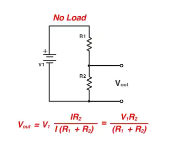
To use the calculator well, know its inputs. These are input voltage (Vs), resistor values (R1 and R2), and output voltage (Vout). Vs is the total voltage given to the circuit. R1 and R2 are the resistors that split the voltage. Vout is the voltage you want to get or use. For example, to turn 5 volts into 3.3 volts, pick R1 and R2 carefully. Understanding these inputs helps you divide voltage correctly.
Avoiding Mistakes in Inputs
Wrong inputs can give bad results. Common mistakes include mixing up R1 and R2 or using wrong units. Sometimes, outside factors like heat changes can affect accuracy. For example, in temperature circuits, thermal shifts can cause errors. Ratiometric measurements can help by reducing power supply changes. Always check your inputs before using the calculator. Make sure resistor values match the voltage you need.
| Figure | Description |
|---|---|
| 2 | Circuit for measuring absolute temperature with a voltage divider. |
| 3 | Circuit for ratiometric measurements to improve sensor accuracy. |
| 7 | Errors caused by changes in Rs, Vdd, and Vss. |
Tips for Correct Data Entry
Entering data correctly gives better results. Follow these tips:
Use the '10% Rule' to keep voltage steady and save power.
Check resistor values with a multimeter before entering them.
Don’t round numbers too much to avoid mistakes.
Check the input voltage direction to avoid wrong results.
By following these steps, you’ll get accurate voltage outputs. This is key for circuits that need precision. Mastering this step helps you use the voltage divider calculator confidently in your projects.
Step 2: Understanding Results from a Voltage Divider Calculator
Grasping the Output Voltage
The output voltage is the part of input voltage across R2. It depends on the resistor ratio and input voltage. For example, if R1 equals R2, the output is half the input. This follows the voltage divider rule, based on Ohm's law. It explains how resistors split the input voltage.
You can test different resistor values using the calculator. This shows how resistor changes affect the output voltage. By learning this, you can design circuits with exact voltage levels for many uses.
Checking Result Accuracy
Accuracy matters when reading calculator results. First, recheck your input values. Ensure resistor values and input voltage fit your circuit. Use a multimeter to measure R1 and R2, as small differences may exist.
Then, compare the output voltage to what you expect. If they don’t match, think about factors like temperature or extra parts. For example, adding a load can change resistance and output voltage. Knowing these effects helps you adjust and confirm accurate results.
Fixing Common Problems
Sometimes, voltage divider results can be tricky. A common problem is how a load affects the circuit. Adding a load changes resistance, causing unexpected voltage levels. This is important in areas like car electronics needing exact voltage.
To fix this, find the issue. Check if the load causes a big voltage drop. Adjust resistor values to balance the load. Online forums like EEVblog suggest using buffer circuits to steady the voltage. Solving these problems ensures your voltage divider works well and reliably.
Step 3: Using Voltage Divider Results in Real Circuits
How Voltage Dividers Are Used
Voltage dividers are useful in many electronic projects. They help control and measure voltage in circuits. Here are some examples:
LED Current Controller: A voltage divider sets the voltage for a transistor. This keeps the LED safe by limiting its current to 20 mA.
Finding Unknown Resistance: Use a voltage divider to calculate an unknown resistor. Pair it with a known resistor, then use the input and output voltages to find the value.
These examples show how two resistors can make circuit design easier and more accurate.
Changing Resistors for Desired Voltage
Changing resistor values changes the output voltage. For example, increasing R2 while keeping R1 the same raises the output voltage. Testing proves this works. Using a potentiometer in a 3-resistor divider lets you adjust voltage between 3 and 5 volts. This gives better control than using one potentiometer alone.
When building circuits, try different resistor pairs with a voltage divider calculator. This helps you get the exact voltage you need. Always check resistor values with a multimeter to avoid errors.
Keeping Circuits Efficient and Stable
To save power, pick resistor values that reduce energy loss. The "10% Rule" says the divider current should be ten times the load current. This keeps the load from affecting the output voltage.
For stability, think about outside factors like heat. High temperatures can change resistor values and mess up the voltage. Use resistors that handle heat well. In sensitive circuits, add a buffer amplifier to keep the voltage steady, even if the load changes.
By following these tips, you can make circuits that work well and last longer.
Learning to use a voltage divider calculator is simple. First, enter correct values for accurate results. Then, study the results to see how the output voltage works. Finally, use these results in real circuits and make changes to get the voltage you need. By doing this, you can design and fix voltage divider circuits easily.
To improve your circuits, use high-quality parts. Arrange feedback paths carefully to avoid signal problems. Changing resistor values can help you get the exact voltage needed. These steps make your circuits more accurate and reliable.
Check out other tools and guides to learn more about voltage dividers. With practice, you’ll be ready to handle harder circuit designs and get steady results every time.