These measurements have a wide range of applications and play a vital role in the analysis of a circuit. For example, finding out the possible faults in an electronic device or component (capacitor). In several ways, a digital multimeter can be used to check the condition of a capacitor, which can help find faulty capacitors or other components in a circuit or device. Let’s discuss in detail about the capacitor, its working, applications, and most importantly how to test a capacitor with a multimeter.
What is a capacitor?
As we start learning capacitance testing through a multimeter, one must know about capacitance, Which is defined as the energy storage capacity of a capacitor, Q1 and Q2 are the charges that exist on the plates of the capacitor, these are +q (positive) & –q (negative). The charge given to these conducting plates determines the electric field in the region between the plates, As the electric field is proportional to the potential difference (V) we can calculate the capacitance of the capacitor by the following relation

The above-mentioned constant of proportionality is known as the capacitance(C) of the capacitor. So in other words we can define” the ratio between changing potential differences to changing electric charge of an electrical system” known as the capacitance. The steps involved in the testing of capacitance are given below in detail. So simply we can define a capacitor as an “energy storage device”.
I. Capacitance Test of capacitor:
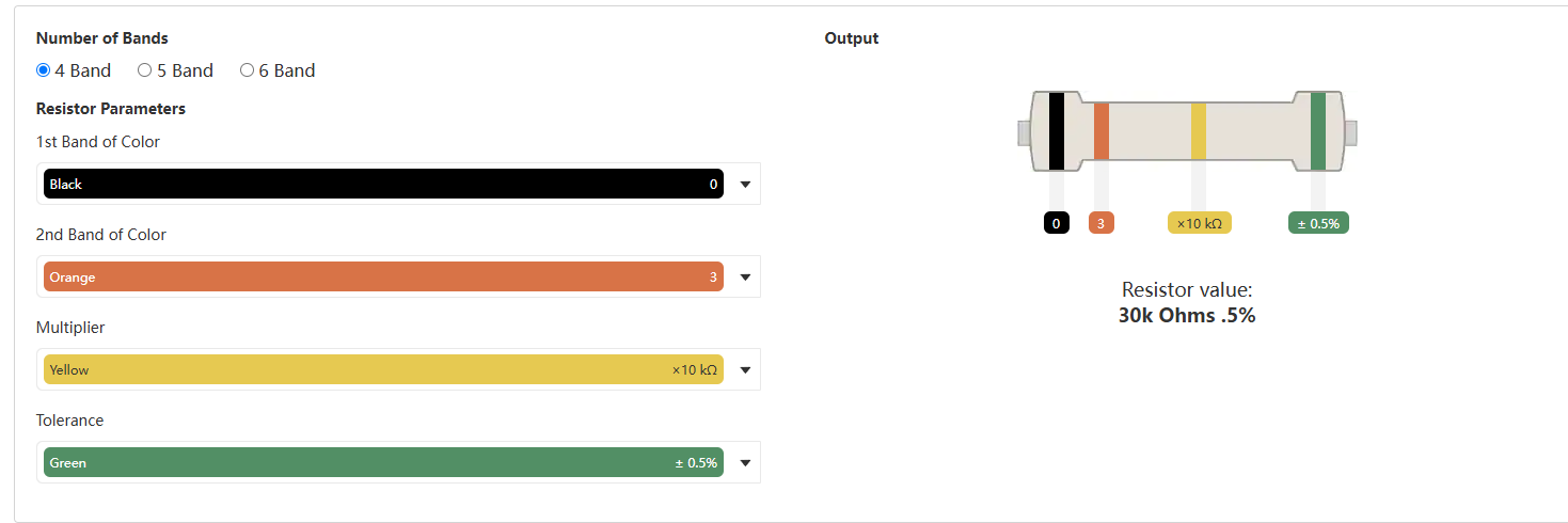
As we know capacitor works on the phenomenon of storing electric charge between two of its closely packed plates that are isolated from each other. There exists a very common phenomenon of capacitors that when power is removed from a circuit equipped with a capacitor, it can be still charged, and possibility of getting an electric shock in there. So the first step to consider while testing a capacitor in any condition or its parameter is discharging of the capacitor. After removing the circuit board to discharge a capacitor a relatively high-value resistor is connected with it e.g. 20 k Ω, Such a high-value resistor is connected for a few seconds to discharge a capacitor properly as shown in the picture below

Figure 1 Discharging of a capacitor with a high-value resistor
After discharging the capacitor properly the second step involves setting the multimeter by rotating the selector on capacitance mode. In some cases, the capacitance option isn’t available in the multimeter so make sure you are using the multimeter equipped with a capacitance measuring option in it. In case our device under consideration has more than one value, then we must select the relatively high rating range of capacitance value to get a correct reading. As shown in the figure below.

Figure 2 Capacitance mode symbol on multimeter
Now we are ready to move our next step of connecting the probes of the multi-meter with both terminals of the considered capacitor for testing purposes. Here we must consider a very important element of polarization of capacitors occurring in the container like capacitors (electrolytic capacitors), so it's very important to identify the positive and negative terminal of the capacitor. Now we will connect the probes as shown in the figure below with the terminal of the capacitor after the identification of its positive and negative terminal. The screen will show us the capacitance value in a few seconds after completing the cycle of sending a current value to charge the capacitor and measuring a voltage that appears across its terminal after charging. As shown in the figure below

Figure 3 Connection of probes with terminals of capacitor
II. Voltage Test:
Measurement of voltage across the terminal of the capacitor gives us an idea about the charge storage capacity of the capacitor. It helps us to understand that a capacitor has an accurate amount of charging while we are using it in our desired circuit. So we can detect if our capacitor is malfunctioning and any disability of the capacitor that is affecting the circuit performance. As well as it also gives us an idea of whether our capacitor is storing charge properly or damaged.
The steps involved in testing the voltage are discussed in detail, firstly as mentioned above discharging of the capacitor is very necessary. Especially when we are dealing with the polarized capacitor we must deal with this carefully.
After discharging connect the capacitor terminals to the power supply and make sure with the help of the multimeter that the current is flowing properly through the circuit, after supplying power to the capacitor, if it working fine it will hold a value of voltage across its terminals equivalent to the volts of our supply. For example, if 12 V is supplied through the battery the multimeter will show equivalent value at its display after connecting probes. And this voltage drops to 0V as our capacitor rapidly discharges. On the other hand, if we are unable to get any value on the display, shows the capacitor we are testing is faulty.

Figure 4 Apparatus for voltage testing with multimeter
III. Resistance Test:
In measuring the resistance, the first step of discharging the capacitor involved is the same as for all other measurements. Once we are done with the discharging we will rotate the selector to turn on the resistance-measuring mode of the multimeter. As shown in the pic below

Figure 5 Resistance mode on multimeter
Then we will connect the probes of the digital multimeter with both of the terminals of the capacitor (negative and positive). Now current will flow through the capacitor, if the output value of resistance has increased from a very low value to a negligible value it shows that our capacitor is charged and working properly. On the other hand, getting a constant low value of resistance represents a short-circuited and a high constant value shows the open circuit capacitor respectively.
IV. Continuity Test:
The faulty condition capacitors can be tested by the continuity test. Continuity is a type of quick test that we perform to check whether our circuit is open or closed. Continuity is only shown by a component when its circuit is complete. In other words, switched on for the circuit, and it is closed. After completing these steps we will hear a sharp beep sound in some multimeter equipped with LED we see it blinking as well. If none of the cases happens our capacitor is faulty.

Figure 6 Apparatus for Continuity test
Applications of a capacitor:
Capacitors have several applications as per their requirements, one may have a good stability level, another can have good current capabilities and some are specifically for superficial temperature coefficient states. For any specific application, we can make an electronic circuit operate at its best by choosing the appropriate capacitor for it. Various applications of a capacitor used in different industries are discussed in detail below.
I. As an energy storage device:
As we know the energy storage capability of a capacitor connected to an electric circuit is its primary application. It can still consume energy when it's disconnected from a circuit, so it works as a temporary battery. While the batteries are being changed, to control the power supplies in electric devices we use the capacitors, by this we can avoid losing our data in volatile memory.
II. In weapons and pulsed power:
To fulfill massive electric current levels for many pulsed power devices, we construct capacitors with low-inductance and high-voltage functionalities. These devices include particle accelerators, generators, pulsed lasers, and electromagnetic gadgets.
III. In power conditioning:
Power conditioning is widely used in power supplies to ease the outcome of a rectifier whether it is complete or half. The capacitance of a capacitor plays a vital role in this regard. As the pump circles generate high voltages, so capacitors assist in this process by storing the energy element.
For signal and control circuits the capacitors generate smooth current fluctuations, that’s why the DC power circuit of electronic devices are mostly connected in parallel with the capacitors. For example, several capacitors are implemented in the electrical audio applications to put down the power line before it enters the electric circuit. The capacitors bypassing the AC from the power source act as a local store for DC power supplies. Therefore car audio devices are equipped with capacitors when a car engine's battery resistance is met by a stiffening capacitor.
IV. As a power factor correction capacitor:
Power factor correction is done with the help of capacitors in several power supply distributions Instead of Farad as the unit for this capacitor, the unit is usually measured in the VA unit (volt-amperes). The purpose is the prevention of inductive loading from the transmission lines and appliances like motors to get the load to appear to be essentially resistive.
You may notice significant sets of capacitors installed at various load centers (usually in big buildings or societies) that require high electrical power consumption. In high-voltage DC transmission connections, power factor correction capacitors have pre-installed tuning inductors to overcome the flow of harmonic currents that could otherwise be added to the AC power system and damage the equipment.
V. As a safety device:
The storage of massive amounts of energy could be dangerous and if not handled correctly with safety measures, capacitors are designed and developed. Disastrous electrical shocks and even destruction of equipment can happen with this tremendous amount of energy level if, from the power source, the capacitor gets disengaged for a significant amount of time. So it is always advised to discharge the capacitor before operating any electrical system where capacitors are attached.
Electrolytic capacitors in certain conditions can break suddenly, most commonly when the voltage on a polarized capacitor is altered. Capacitors also break abruptly as the dielectric material volatilizes or splits down in high voltage or high power devices.
VI. As a hold-up capacitor:
Hold-up is utilized to give a power supply for a short time to an electric circuit. Before the development of these capacitors small rechargeable batteries were used for this purpose. The capacitors can give a viable alternative as compared to the batteries because they undergo consequences and life restrictions.
Nowadays the upper capacitors play a vital role in massive capacitance level requirements, to allow many circuits to remain powered during the unavailability of power. They provide an outstanding level of performance and are comparatively economical.
VII. As coupling and decoupling RF devices:
The same fundamental laws are applied in the designing and development of RF coupling and decoupling and are required for the decoupling and coupling of capacitors. However, the appropriate RF performance is required for the capacitor used in the RF applications. However, at lower frequencies, the performance may vary.
Usually due to dropping in performance with an increase in the frequency people don’t prefer to use the electrolytic capacitor often used for systems operating at a frequency of more than 100 kHz. Performance declination is prevented by using ceramic capacitors, because of their ability to provide outstanding RF performance, specifically the MLCC surface-mounted capacitor.
VIII. Smoothing capacitor applications:
Decoupling capacitors are effectively equivalent to smoothing capacitors, but typically this term is used by people in conjunction with power supply. The incoming waveform is not always smooth while receiving the line signal from the transformer and a rectifier. This value ranges from starting point (zero) to endpoint (peak) voltage. It can operate as a DC voltage when connected to an electric circuit. At this point, the decoupling or smoothing of DC voltage is done.
- 1.
How we can check that the capacitor is working properly?
Ans: With the help of a multimeter we can perform several checks to know whether our capacitor is working properly or not. These tests include voltage testing, capacitance testing, and continuity check.
- 2.
What is the method of checking the rating of the capacitor?
Ans: Farad is the unit to measure the capacitance of a capacitor. This capacitance is the ability of a capacitor to store the electrical charge provided to it. Usually, the ratings are given on the capacitor. But in case ratings are not mentioned we can check it by all the parameters through the multimeter.
 Paul George
Richard Electronics guest author, a Mechatronics engineer and a professional researcher, designer, developer and manufacturer for 3d Cad and PCB. I believe in efficiency, effectiveness and quality of work, and my aim is to provide complete one-roof solutions to complex mechanical and electrical design systems. I have a well-equipped lab with state-of-the-art technology for doing research and providing.


06 June 2026

07 May 2026
17 April 2026

02 April 2026
02 April 2026